C2 PROJECT
C2 Photo Album
album:August 2019
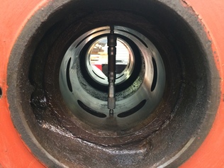
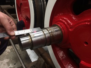
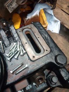
Measuring the diameter and worn shape of the valve bores using an internal micrometer. Measurements were taken at a total of 24 locations.
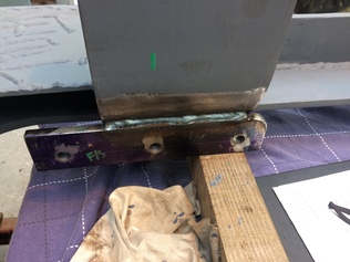
Andrew welded some additional brackets to the new crash beams - these will carry rubber rail sweeps to remove small items of debris.
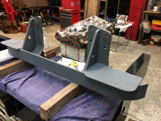
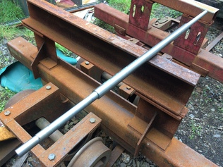
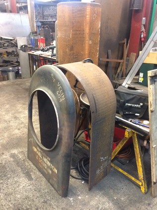
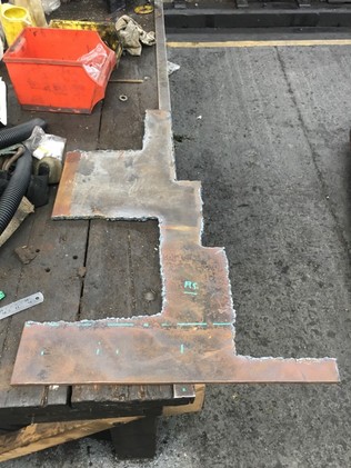
The new crashbeam for the front of the loco, based on the original design but narrowed to suit the change in gauge. The nearest footstep with Mandarin lettering was recovered from the original.
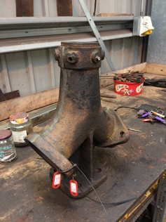
During the reorganisation of our storage shelves, we came across the blastpipe casting which was still in a filthy state. Caleb did a great job removing the grime and grinding off some of the original casting flash.
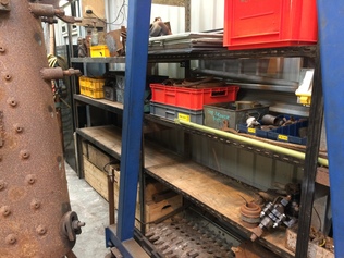
The major reorganisation of our storage shelves has created more space to store refurbished parts, and the remaining unrepaired components are stored more logically.
Now that we have finalised the packing needed behind the cylinders and motion brackets, we were able to complete the drawings for the draincock linkage weighshaft and the reverser weighshaft. Dave 2 manufactured the draincock weighshaft and we will order material for the reverser weighshaft in time for next month.
We have a spare set of valve liners, which we will not need at this stage but may be useful in future. Here Dave 1 cleans them up so we could check the dimensions..
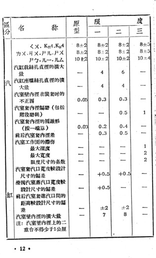
The Chinese Forestry Railways' steam loco overhaul manual provides requirements for the variation in valve bore shape. There are limits on differential diameters, the extent of barrel-shaped wear, conical wear, and surface defects. We will correct these by skimming the valve bores on the horizontal borer. The important dimension for us is the bottom one on this page: the permitted enlargement in bore diameter. The nominal is 150mm; the maximum permitted for a loco after heavy overhaul is 150+7mm, and for intermediate overhaul is 150+8mm.
Last month we wrote about our decision that we would need a new boiler. We may subcontract this job out, but another option would be to do much of the work ourselves, working with a coded welder. Here are some of the major components for Velinheli's new boiler, currently being built at Boston Lodge.
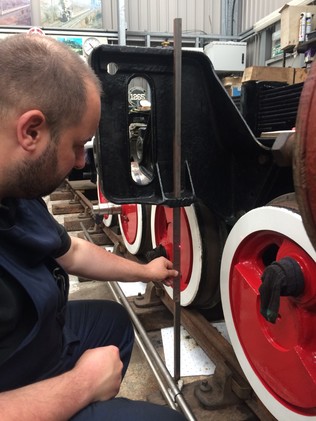
Checking the alignment of the cylinder with the driving crankpin. When the proposed cylinder packing plates are accounted for, the alignment all looks good and consistent with our expectations.
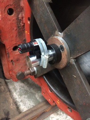
The X-shaped jigs previously made by Alan locate a stanless steel rod precisely in the centre of each cylinder. We mounted a laser to this rod, allowing us to project the line of the cylinder bore backwards. By rotating the rod the laser point describes a circle and the centre of that is aligned with the cylinder centreline.
While the laser setup was installed, we also checked the vertical offset to the motion bracket.
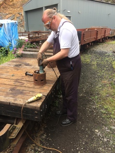
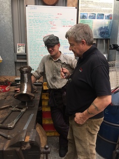
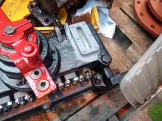
The blastpipe has a removable nozzle, allowing alternative sizes of nozzles to be fitted. However, years of heat and corrosion had seized the fixing bolts and the nozzle itself. Here, Jon and Caleb discuss approaches for dismantling.
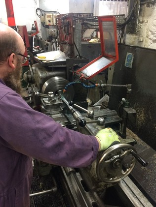
Dave 2 machines the new draincock weighshaft.
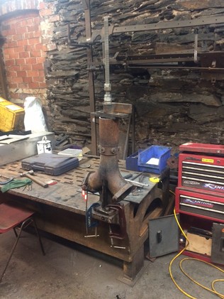
Dave 2 and Tom created a setup to extract the blastpipe nozzle, enabling the nozzle to be pulled upward while heat was applied.
And Finally...
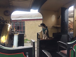
During the busy summer season, the railway always seems short of loco crews, and Paul, Sam and Jon were all active on the footplate over the weekend. Rumours of a programme to train other intelligent species to cover footplate duties are apparently untrue.
During the busy summer season, the railway always seems short of loco crews, and Paul, Sam and Jon were all active on the footplate over the weekend. Rumours of a programme to train other intelligent species to cover footplate duties are apparently untrue.
The fireman's side lubricator sight glass showing the new gaskets and spacer assembly.
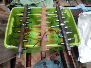
10 pumps have been fitted to the driver's side lubricator along with the slide bar and sliding bearings / gaskets. The photo of the slide bars shows the old driver's side one on the left with two broken ball ends. The center and right hand ones were acquired as spares. The right hand one has now been cleaned up and fitted to replace the broken original.
The fireman's side lubricator sight glass now fully assembled. Apart from fitting the ratchet mechanism this lubricator is now oil tight.
This unpromising piece of scrap was the raw material for the new coupling rod knuckle joint pin retaining covers. Hopefully at the next working party we will be able to show the completed machined components.
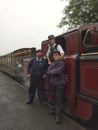
Paul at Blaenau Ffestiniog with the rest of the crew of the last chippy train of the year: fireman Alastair and guard David.